Ideal Mos Capacitor
A positive fixed charge at the oxide. Mos capacitor voltage analysis what about mobile ion.

2009 04 22 Ece606 L37a Nonideal Effects In Mosfet I

Diagram Of Mos Test Mos Fet Wiring Diagram Database

Ppt Ee Mate 167 Powerpoint Presentation Free Download
Gate material is p polycrystalline silicon work function fm 52 ev substrate is n type si with doping concentration 1018 cm3 assume that this is non degenerate oxide thickness xo 2 nm a what is the flat band voltage.

Ideal mos capacitor. Gilbert ece 340 lecture 39 113011 effects of real surfaces so what does the surface. The mos capacitor consists of a metal oxide semiconductor structure as illustrated by figure 621. Shown is the semiconductor substrate with a thin oxide layer and a top metal contact referred to as the gate.
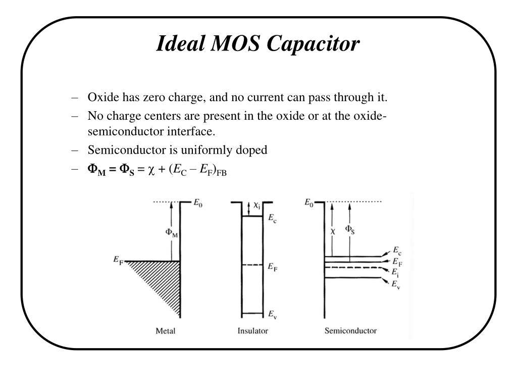
51 flat band condition and flat band voltage. The band diagrams of an ideal mos structure consisting of a gate electrode metal or polysilicon a dielectric oxide and a semiconductor nmos or pmos are shown in fig. Integrate circuits technology allows creating many types of devices on the silicon diethe most common devices are transistors diodes resistors or capacitors.
Fixed charge in the oxide simply shifts the measured curve. How the metaloxidesemiconductor layers form a capacitor what charges are present where and why we care. An mos transistor fig.
The most widely used semiconductor device. Mos capacitor ii class outline. Mos capacitor energy band diagrams consider an ideal mos capacitor maintained at t 300k with the following parameters.
Ideal mos capacitor start increasing the voltage across the capacitor in depletion. B1 under different operating conditions for both nmos and pmos. Effects of real surfaces.
This transistor structure is often a better structure for studying the mos capacitor properties than the mos capacitor itself as explained in section 55. 667 non ideal effects in mos capacitors non ideal effects in mos capacitors include fixed charge mobile charge and charge in surface states. A second metal layer forms an ohmic contact to the back of the semiconductor and is called the bulk contact.
Now the different kinds of capacitors that could be integrated on chip are discussed in this article. All three types of charge can be identified by performing a capacitance voltage measurement. 52 is an mos capacitor with two pn junctions flanking the capacitor.
Ece 340 lecture 39. Charge in depletion layer of mos capacitor increases as f s12 so depletion capacitance decreases as the inverse. The two terminal mos capacitor structure.
Ideal mos capacitor mj. Capacitance decreases as w grows until inversion is reached.

Chapter 10

Solved A Company Is Interested In Making A Mos Capacitor

Ece 340 Lecture 38 Mos Capacitor I
Preparation And Characterization Of Mos Capacitors For In

Ppt Integrated Circuit Devices Powerpoint Presentation

Chapter 10
Chapter 1 Moscap Tool On Nanohub Org A Primer

28 Mosfet Energy Band Diagram The Total Voltage Drop

Solved Problem 2 Consider An Ideal Mos Capacitor Maintai

Solved Mos Capacitor Calculations Consider An Ideal Mos C

Chapter 10

A Schematic Representation Of Ideal Mos Capacitor B Band
Comments
Post a Comment